
Air Louvers
March 10, 2020
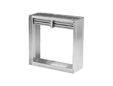
CD36 LOW LEAKAGE CONTROL DAMPER GALVANIZED STEEL
March 10, 2020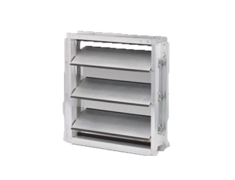
CD60 LOW LEAKAGE CONTROL DAMPER
The CD60 offers sturdy, steel construction with interlocking frame design, enabling it to lock together without bolts, screws, or rivets that could shake loose. It also features Frame corners that are internally braced to reduce racking. Axles that positively lock to blades without screws or welds. Non-stick, noncorrosive bearings that assure long life and ease of operation. Airfoil blades, which have greater strength, produce less sound, greater sealing ability, and static pressure loss. Concealed linkage to reduce turbulence, which provides lower pressure drops and reduces noise. The CD50 damper is an extremely low leakage damper designed for use in medium to high-pressure commercial HVAC systems. It was the first AMCA licensed low leakage damper and features: Airfoil blades for greater strength, less noise, and less pressure loss,
Extruded aluminum construction and Concealed linkage for low maintenance and less turbulence.
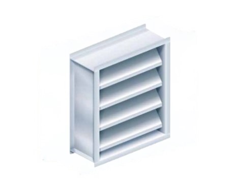
APPLICATION
The CD60 is a low leak, galvanized steel damper designed with airfoil blades for higher velocity and pressure HVAC systems. It meets the leakage requirements of the International Energy Conservation Code by leaking less than 3 cm/sq. ft. at 1″ of static pressure and is AMCA licensed as a Class 1A damper.
Airfoil blade design for low-pressure drop and less noise generation.
- One-piece interlocking frame design to reduce racking.
- Positive lock axles, noncorrosive bearings, and shake-proof linkage for low maintenance operation.
- Blade edge seals mechanically lock into the blade for superior sealing.
OPTIONS
- Factory-installed, pneumatic, and electric actuators.
- Enamel and epoxy finish.
- SP100 Switch Package to remotely indicate a damper blade position.
- Heavier frame construction with a U-channel frame.
- Front, rear, or double flange frame with or without bolt holes.
- Face and bypass configurations.
NOTE: Dimensions shown in parenthesis ( ) indicate millimeters. Units furnished approximately 1/4″ (6) smaller than the given opening dimensions.
The CD60 may be used in systems with total pressures exceeding 3.5″ by reducing damper section width as indicated. Example: Maximum design total pressure of 8.5″ w.g. would require CD60 damper with a maximum section width of 36″ (914). Pressure limitations shown above allow maximum blade deflection of 1/180 of span on 60″ (1524) damper widths. Deflections in other damper widths (less than 48″ [1219]) at higher pressures shown will result in blade deflection substantially less than 1/180 of the span.
Reviews
There are no reviews yet.